HIGH-QUALITY INNER CATHODE
THE HEART OF THE CATHODE CELL
The inner cathode is the most critical part in the electrolysis process. Can-Tech has a long history of engineering inner cathodes and has succeeded in maintaining a high level of performance even after years of operation. More than 46 years of engineering and testing have proven that Can-Tech leads the field in construction of diaphragm cells. None of our competitors have succeeded in developing a better inner cathode than Can-Tech.

The Can-Tech diaphragm cell is the most technologically advanced cell for the electrolytic production of chlorine and sodium hydroxide. The monopolar electrolyzers have parallel-assembled anodes and cathodes. Thanks to the production technique used and high-quality screening. Can-Tech diaphragm cells have the highest product outputs on the market.
HIGH-CONVERSION CATHODES FOR BETTER PERFORMANCE
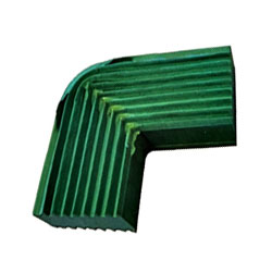
JP Heavy-Duty screens inside
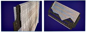
The outer cathode is made of steel and the inner cathode incorporates JP Heavy-Duty screens. These flat-wire screens are specially designed for high performance. Can-Tech wire screens have flatness tolerances that are unique in the market and have not been achieved by any competitor screen. Even after decades of operation, the Jonge Poerink Heavy-Duty screens are still flat. This technology guarantees the highest conversion rates. MSR Can-Tech Cathodes is the only manufacturer with these screens.


Perfect fixation between copper and steel
The explosion bonding technology, which has been in use for more than 46 years, ensures a perfect bonding between the copper and steel plates used in the outer cathode. This results in zero resistance between steel and copper.
ULTRASONIC TEST REPORT - CONTINUATION SHEET | |||
Description: | Disbonding | ||
Client: | Confidential Client South Africa | Location: | South Africa |
Manufacturer: | MSR Can-Tech Cathodes | Contact Person: | William Killian |
Drawing / Line No.: | N/A | Equipment No.: | DX 229 |
Material: | Copper / Mild steel | Percentage Disbonded: | 30.17% |
Order / Job No.: | 1550 | Cathode Can Side: | Hot side |
TEST RESULTS | |||

ULTRASONIC TEST REPORT - CONTINUATION SHEET | |||
Description: | Disbonding | ||
Client: | Confidential Client South Africa | Location: | South Africa |
Manufacturer: | MSR Can-Tech Cathodes | Contact Person: | William Killian |
Drawing / Line No.: | N/A | Equipment No.: | DX 229 |
Material: | Copper / Mild steel | Percentage Disbonded: | 0.00% |
Order / Job No.: | 1550 | Cathode Can Side: | Hot side |
TEST RESULTS | |||

Long Lifetime
MSR Can-Tech Cathode produces cathodes with utmost attention to qualify and a guarantee of optimal lifetime. A special stress-relief treatment also avoids cracks in the metal.


Revolutionary inner construction
We have developed a unique inner-cathode construction with a short and homogenous current path which results in a lower voltage drop.
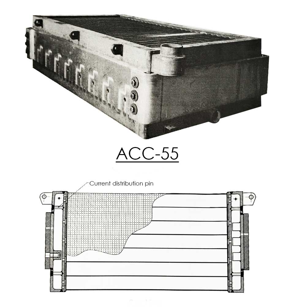
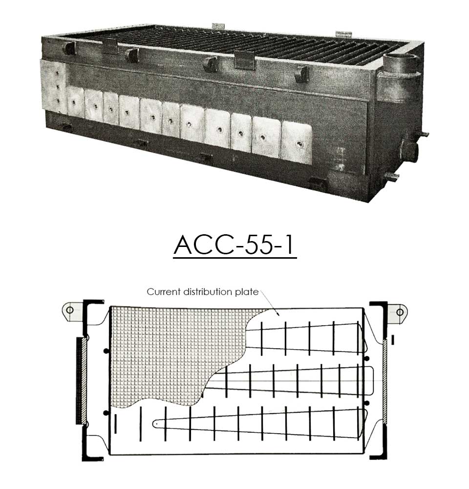
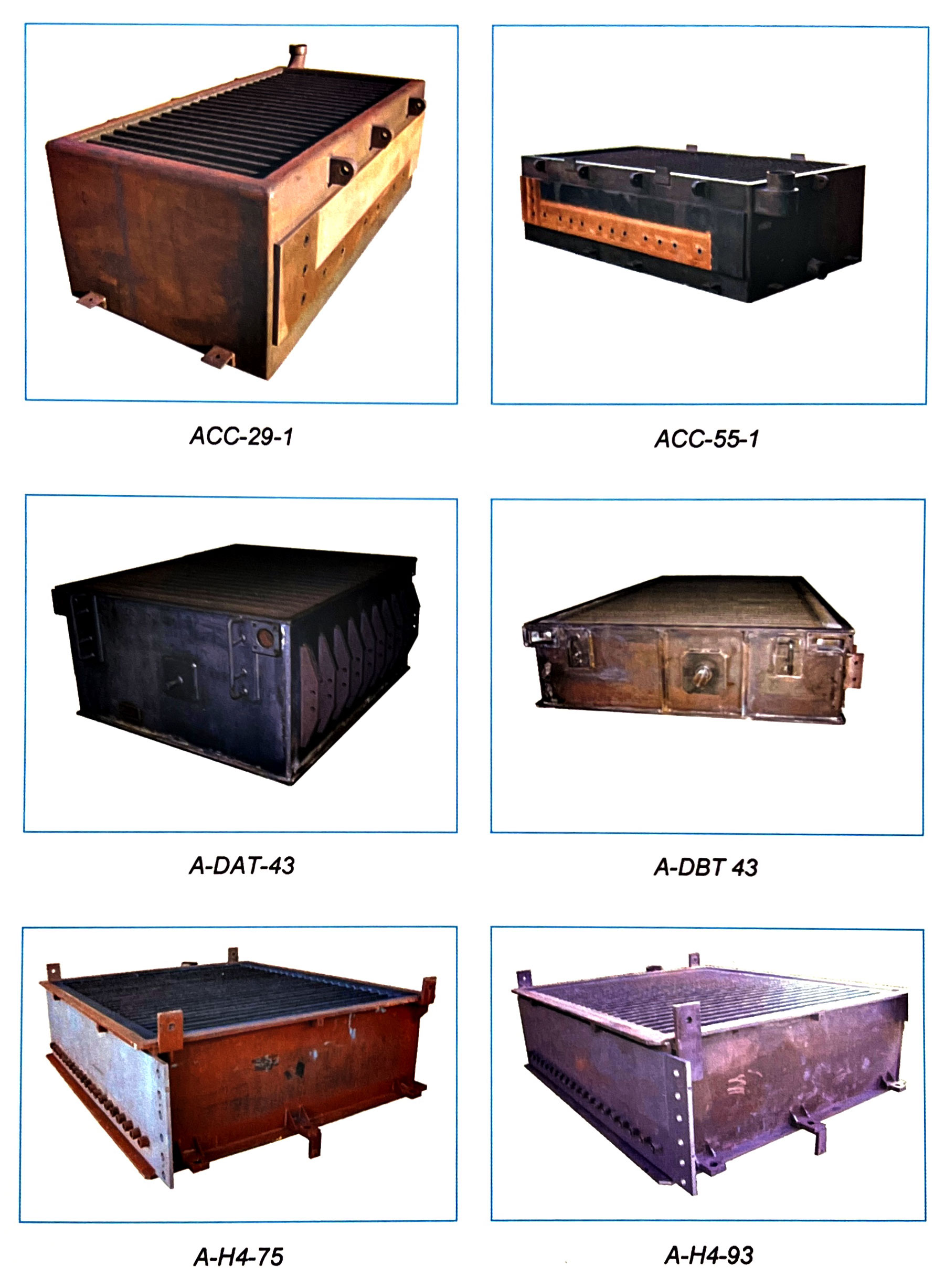
Can-Tech offers several designs of diaphragm cells to fit specific production requirements. Besides the ACC-29 and ACC-55 cells, Can-Tech also produces other advanced types.
In the following table an overview is given with their specific properties.
ACC 55-1 | ACC 29-1 | A-DAT-43 | A-DBT-43 | A-H2A-50 | A-H4-75 | A-H4-93 | |
Anode Surface [m2] | 55 | 29 | 43 | 43 | 43 | 65 | 80 |
Outside Dimensions LxWxH [M] | 2,86 x 1,53 x 0,82 | 2,16 x 1,10 x 077 | 1,80 x 1,54 x 0,80 | 2,84 x 1,54 x 0,44 | 2,15 x 1,68 x 0,72 | 2,64 x 2,33 x 0,74 | 2,64 x 2,33 x 0,74 |
Remarks:
All the cathodes mentioned are suitable for asbestos or synthetic diaphragms.
The cathodes are available for one or two Cu / Fe bonded side plates.
Cell parts
The main diaphragm cell parts are:
- The base, with expandable anodes
- The cathode
- The diaphragm
- Cell cover (or head)
- Base cover and gaskets
The base with expandable anodes
The base is made from a thick copper plate (approximately 20 mm) provided with openings for the connection of the expandable anodes. The anodes areconnected with the under side of the base by copper nuts. Between the anodes and the base a rubber sheet is placed. Base of the anode is titanium, mainly coated with ruthenium oxide. This type of coating provides a lower decomposition potential, and thus lower cell voltage. A lower potential results in lower energy costs. The life time of the anode coating depends on process quality (amongst other; current density, brine quality, diaphragm quality, stop and start procedure). With good operation and an average current density of approximately 2.0 to 2.2 kA/m? a lifetime expectation of 10 to 12 years is reachable. The coating thickness can be checked periodically by radiation measurements.
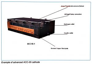
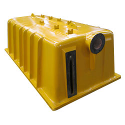
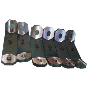
The cathode
The Can-Tech Advanced Cathode Can is constructed of steel with severalinternal connections and fully welded with wire screen tubes. On one side copper and steel plates are full explosion bonded which gives a perfect fixation and current distribution. At the lower side of the cathode a connection is made with a revolving pipe for discharging the cell liquor. The position of this pipe, and thus the height of the cell liquor in the cell, is adjustable. At the upper side of the cathode the hydrogen gas discharge to the header is connected. The hydrogen gas space in the cell also depends on the position of the cell liquor pipe.
During operation the wire screen tubes must be fully covered by a diaphragm to prevent connection with the anolyte side.
The diaphragm
The diaphragm in combination with expandable anodes can be made from asbestos fibers plus Teflon fibers. In connection with environmental problems in some countries, asbestos can be replaced by synthetic fibers materials, such as zirconium oxide or titanium oxide combined with Teflon fibers (Polyramix or Tephram). Diaphragms based on synthetic materials are more expensive. The diaphragm life time with synthetic materials should be about 3 times longer compared with the same preparation costs of asbestos diaphragms.
Principle of the preparation of a diaphragm
First a bath of slurry (asbestos, Teflon or synthetic fibers) is prepared, by mixing fibers of certain graduated length in caustic liquor or other liquids. A point of importance is always to realize a stable and homogeneous dispersion before depositing of the diaphragm on the cathode screen. After immersion of the cathode into the depositing tank and connection with vacuum equipment depositing can start. Application of vacuum to the cathode according to a specified time-vacuum cycle forms a coating of a fiber mixture on the cathode screen. After drying and curing of Teflon fibers (PTFE till 320°C) the diaphragm becomes strong mechanical and chemical resistance by fusion.
Cell cover
The traditional cell heads are produced from PVC-polyester and strengthened outside with vinyl-ester with glass fiber. The lifetime is about 5 to 7 years. A disadvantage of using these materials is the chemical reaction of chlorine with PVC and plasticizers which forms less agreeable by-products. Better materials with longer life time (> 10 years) are PVDF (Poly-Vinyl-Di-Fluoride and Telene (dicyclopentdiene). These materials do not react with chlorine. The improved spring loaded clamps assure a good fixation of the cell cover (head) to the diaphragm cell. The use of PVDF and Telene in combination with the chosen construction results in safe operation and long lifetime of the cell and cell head.
Base and gaskets
The function of the base cover is to form isolation between the anode and cathode compartment, and for protection of the copper bottom against anolyte liquid. The traditional used material is neoprene. Because of the short lifetime of this material the newest covers are made from EPDM. This material has better performance in relation with lifetime and leakage. For the gaskets the same material is used as for base covers. Can-Tech has developed non-leakage gaskets from EPDM. These gaskets form a good and safe packing between cell head and cathode and between cathode and cell bottom.
Cathode Design
Can-Tech has developed and constructed new cells with the following properties:
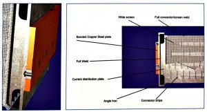
- The Advanced Cathode Cells have vertical thick steel distribution plates, placed in the centre of the wire screen cathode tubes. These distribution plates have channels and are fully welded to the cell on both the top and the bottom. Internal connections with the wire screen by vertical placed strips guarantees excellent load distribution.
- Excellent welded wire screen on internal strips and plates.
- The current distribution plate is welded directly behind the copper plate.
- The copper/steel plates are full explosion bonded which guarantees a perfect fixation.
- For all internal connections thick steel is used.
- The ACC cells are equipped with JP Heavy Duty Screening which ensures a high conversion rate. The specially woven wire screens are strong and remain flat even after more than decades of operating. The JP Heavy Duty screening is suitable for use in every type of diaphragm cell.
Advantages of advanced cathode construction are:
- Homogeneous temperature distribution, inside and outside the cathode.
- Excellent current distribution.
- Low electrical resistance
- Low voltage drop
- Very stable wire screen, even after many years.
- The electrical cell resistance will be constant, almost during the whole lifetime of the cathode.
- Guarantee for homogeneous and stable distance between anode and cathode.
- Longer lifetime of cathodes, which can reach up to twenty years in the field.
- Inside the cathode can only steel is used and therefore no strange metal pollution in cell liquor
Details of internal construction and connections of wire screen, distribution plate inside the tube with open channels
The current distribution plate is welded directly behind the copper plate
Safety aspects
The internal connection strips are constructed vertically to realize hydrogen discharge to the header with minimal resistance. This results in less pressure fluctuations in the cathode compartment.
Advantages:
- Less chance on short-circuit and cell damage.
- Longer and safer diaphragm lifetime.
- Less hydrogen in chlorine gas, and therefore less chances on hydrogen explosions.
Safety and long cathode lifetime
Hydrogen in chlorine gas can be explosive if the H2 concentration is more than 4 vol %. Necessary for an explosion is always an ignition source.
The sources of hydrogen formation in chlorine gas of diaphragm cells are:
- Diaphragms
- Cathode quality
- Process circumstances
Causes of high hydrogen in chlorine may be:
- Plugging of holes in cathode screen during diaphragm depositing
- Cathode screen quality (holes, thin wire, bad welds)
- Insufficient differential height between anolyte and catholyte (should be > 35 cm)
- Rust spots on the diaphragm caused by staying too long in a corrosive atmosphere before installation
- Improper application of the diaphragm
- Gas pressure fluctuations. Fluctuations of more than about 10 cm in cell gas can damage diaphragms enormously. This results in lower anolyte levels combined with high hydrogen
- Rust spots through the diaphragm formed by wire screen corrosion during electrolysis stops (iron attack by HOCI and NäOCI). Corrosion of iron wire forms iron oxides (a.o Fe2O3.×H2O, Fe3O4.×H20). Growth of these conductive materials through the diaphragms forms hydrogen, directly in the anolyte space of the cell. Cause of this corrosion process is attack of iron by hypochlorite after an electrolysis stop according to the reaction:
3 HOCl + 2 Fe → Fe2O3 + 3 HCI
MSR CAN-TECH CATHODES
High-Quality Accessories and Cell Parts
As a diaphragm cell specialist, we also offer a range of high-quality accessories. These superior products have been shown to meet highly demanding production requirements.
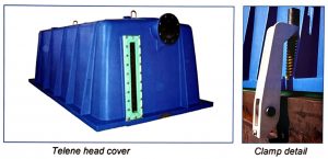
Cell Heads
Our cell heads are manufactures from a special compound known as Telene, which is highly resistant to chlorine even high temperatures. This advanced technology assures you the highest quality standards.
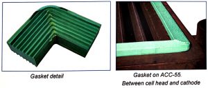
Gaskets
Based on the field experience of our customers, we offer high-grade gaskets. These gaskets, made from a special-grade green EPDM, have a lifetime of up to 5 years, which is necessary for today’s cycle of maintenance.
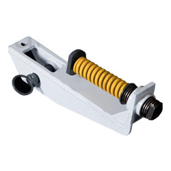
Clamps
To
ensure a good fixation of the cell head to the cathode, we provide specially designed spring-loaded clamps. These provide the perfect connection between cell head and cathode.
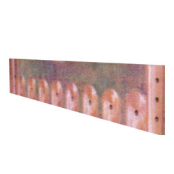 Explosion-bonded copper plates
 Intercell connector
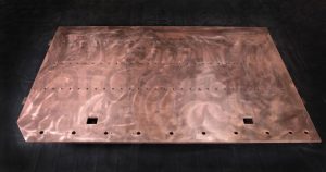 Copper base plate
Electrical current in metals is transported by conductance of electrons (negatively charged particles). As a consequence of the electric tension, the electrons are moving to the highest electric potential and the current to the lowest potential.
Transport of electrical current in liquids occurs via ions.
lons are charged particles, formed when molecules or atoms pick up or yield one or more electrons. For example:
If salt (NaCI) dissoves in water (H;O), the molecules separate in Na (positive ions) and Cr (negative ions).
NaCl + ( H2O ) → Na+ + CI–
Salt + Water (= brine) > Sodium ions + Chloride ions + Water
During electrolysis processes two types of electron transport occur.
- Conductance of electrons in metals;
- Conductance by ions in the brine. In figure [1] the general principle of electric transport and electrolysis of brine is illustrated.
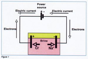
The transport of direct current in brine begins at the anode (positive electrode) and finishes at the cathode (negative electrode) according to following principal chemical reactions.
Anode reaction:
2 CI–→ CI2 +2 electrons
(oxidation of negative chloride lons to chlorine molecules)
Cathode reaction:
2 H20 H2+2 OH– – 2 electrons(discharge of water)
Overall reaction for anode and cathode:
2CI– +2 H2O Ch2 + H2 + 2 OH– or:
2 NaCl + 2 H2O → Cl2+ H2 + 2 NaOH
Salt + Water> Chlorine gas + Hydrogen gas+ Sodium hydroxide
Types of electrolysis processes
Three types of electrolysis are in practice for technical production of chlorine, hydrogen and sodium hydroxide.
The titanium anode coated with ruthenium oxide is the chlorine forming positive electrode. The 3 types of electrolysis are:
- Mercury electrolysis
- Membrane electrolysis
- Diaphragm electrolysis
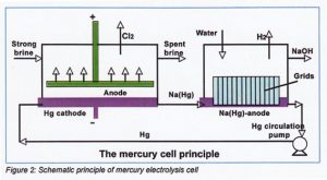
Mercury electrolysis process
The cathode of this type of electrolysis cell is formed by an iron bottom covered with a thin layer of mercury. The anode is faced toward the mercury layer. There is no barrier between cathode and anode. On the cathode mercury bottom sodium amalgam Na(Hg) is formed. This sodium amalgam is transported to a decomposer cell to form hydrogen and sodium hydroxide.
Cathode reactions:
Na+ + electron> Na
Na + Hg > Na(Hg) Sodium amalgan
Decomposer reaction:
2 Na (Hg) + 2 H2O→2 NaOH + H2
Sodium amalgam + Water > Sodium hydroxide + Hydrogen
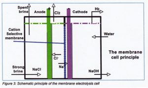
Membrane electrolysis process
Membrane is the separator between anode and cathode compartment. The membranes types used for electrolysis are cation-selective modified. Only positive charged ions are transported through the membrane to the negative charged cathode and forms sodium hydroxide and hydrogen gas.
The negative charged chloride ions are moving to the positive anode and forms
chlorine.
The electrolysers are bipolar constructed with about 100 – 120 internal cells. The depleted brine coming out the electrolysers is saturated in salt dissolvers. Next figure 3 shows the principle of a membrane cell.
Diaphragm electrolysis process
On diaphragm electrolysis calls a diaphragm is placed as separator between anode and cathode compartments. This diaphragm is liquid permeable.
Because the conversion of NaCI into NaOH is less than 100 % it means that the hydroxide solution formed at the cathode is polluted with salt. Normally about 50% of salt is converted into NaOH.
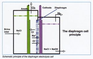
Salt in the cell liquor is removed by evaporation from cell liquor (10% caustic) to 50% caustic. Crystalline salt formed during this process is separated from the hydroxide solution and will be used again as feed for diaphragm electrolysis.
The diaphragm can be prepared from a mixture of asbestos and Teflon fibers or on synthetic base (PMX or TEPHRAM fibers).
Newest cells operate with a cathode current efficiency very close to 100% and an anode current efficiency of approximately 96%.
Brine quality
The sodium concentration in electrolysis brine has mostly a range of 305-320 grams NaCl per liter. This brine feed mosthy originates from 2 sources:
- Directly from the brine purification plant on location.
- From salt dissover, combined with the salt resulting from caustic evaporation.
Most diaphragm electrolysis plants have a second brine purification before the brine is fed to the cells.
This second purification removes the last amounts of magnesium and calcium. These components, if present, can plug the diaphragm. This results in bad permeable diaphragms and therefore a relative short lifetime expectancy. These components are precipitated with sodium hydroxide and sodium carbonate by forming magnesium hydroxide and calcium carbonate, according to the reactions:
Mg2 + 2 OH– → Mg(OH)2 ↓
Ca2+ +2 CO32- →CaCO3 ↓
The formed precipitates can be removed by a filter process (filter clothes or filter candles). Typical values of Magnesium and Calcium in feed brine after second purification are:
Mg < 0.2 mg/l
Ca < 2 mg/l
Power cell room
The cell room is the heart of the electrolysis factory Most plants have 2 circuits with diaphragm cells. The amount of cells per circuit depends on the maximum load required, the cell voltage and the inter cell resistance. The normal maximum circuit voltage of a circuit is 400 Volt. When a maximum load is required of 2.75 kAm2 (80 kA for a ACC-29 and 150 kA for a ACC-55 cell) the individual average cell voltage is about 4 Volt. In this case maximum 100 cells can be build into one circuit. In the case of electrolysis direct current is necessary, transformers and rectifiers are needed. The power of transformers rectifiers per circuit will be 80 x 400= 32.000 kW (32 MW). In following figure [4] the current feed for one circuit is given. Normally more circuits are in operating.
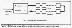
For a safe work environment the connections between cells, facing each other, should be placed sufficiently apart to prevent the possibility of these cells touching.
Function of diaphragm
The most important function of a diaphragm is to prevent mixing of anolyte and catholyte products (chlorine gas, hydrogen gas and cell liquor). The principle of the working of diaphragm cells is to maintain a brine flow from anolyte through the diaphragm into the catholyte, approximately equal to the rate of OH– ion migration from cathode to anode. This flow is adjustable when the level of the liquid of the catholyte is a lower level then the level of the anolyte. In equilibrium situations a continuous operation level difference of > 35cm is usual and should be maintained. This level difference prevents migration of sodium hydroxide to the anolyte.
Because diaphragms are permeable for all liquids, the cell liquor will contain a high concentration of NaCI.
One of the most useful relationships in the study and control of diaphragm cell operation is the salt-caustic ratio or conversion. This is the ratio of weight NaCI to weight NaOH in a given weight of cell liquor effluent. The percent of decomposition is directly calculated from the salt-caustic ratio in cell liquor:
Conversion (Moles NaOH/ (Moles NaOH + Moles NaCI) X 100%
The typical value of the conversion has a range Of 50 – 55%.
The salt-caustic ratio combines in one factor the effects of brine concentration, brine flow rate, current density and alkali concentration. The greater diaphragm uniformity, the better current efficiency can be expected.
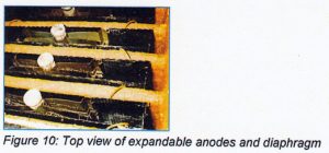
Function of anode
On the anode chloride ions are oxidized to chlorine molecules. The expanded modification and perforated anode plate, coated with ruthenium-oxide provides a low anode potential and hence a low cell voltage.
Reasons lor lower cell voltage
- Use of ruthenium oxide as coating reduces the decomposition voltage for anode reactions.
- The shorter electrolyte distance between anode and diaphragm provides a lower electrical brine resistance. The distance between anode and diaphragm at use of expandable anodes is based on the thickness of the spacers between anode and diaphragm (2-3 mm).
- The perforated anode plate provides a better gas distribution around the anode, and thus a lower gas-hold up. Less gas concentration in liquid means lower electrical resistance.
The benefits of expandable adnodes compared with stable plate anodes are about 0,3 – 0,4 Volt ar 2 Ka / m2 or 225 – 320 kWh / ton chlorine produced.
In figure 10 the expandable anode with spacers placed between anode and diaphragm is shown.
The current efficiency of a diaphragm cell depends among others upon:
- The cathode screen
- Internal current distribution
- Diaphragm quality
- Operation conditions (temperature, caustic strength, anolyte pH)
Typical anolyte pH has a range of 3,5 – 4,5. More sodium hydroxide diffusion through diaphragms results in higher anolyte pH and therefore lower current efficiency.
Oxygen and chlorine evolution are the principal anode reactions.
The various ions which may participate in oxygen discharge are OH– CIO3–, SO42-. en OCI–.
Any oxygen-producing discharge produces an equivalent of H+ ion. Hence in normal operation, it may be considered that all oxygen produced is derived from OH– ion discharge.
The higher the anolyte phH (originated from higher OH– transport to anolyte) the more oxygen will be formed at the anode.
The temperature of the anolyte is approximately 80 – 85°C, depending on brine temperature current density and electrical cell resistance.
Function of cathode
On the cathode, the main reaction is discharge of .
2 H2O → H2 +2 OH– – 2e
Also the reduction of HOCI and OCI– to CI– takes place at the cathode. The temperature of the cell liquor produced is approximately 85- 90°C. This temperature depends on electrical cell resistance, current density and sodium hydroxide concentration in cell liquor.
The cathodes in the diaphragm cells are constructed with JP Heavy Duty Screen. The screen is flattened to provide a large surface and small holes. The pressure differential between anolyte and catholyte liquid level maintains the diaphragm against the cathode support. With the deposited diaphragms, the fibres tend to penetrate into the holes of the cathode structure and to lock the diaphragm to the screen.
Hydrogen bubbles are formed over the entire metal surface. Those formed on the face of the cathode toward the anode must penetrate minute spaces between fiber and metal surface to enter the cathode compartment. Some diffusion of hydrogen through the diaphragm into the anode compartment tends to occur and to result in an undesirable addition to the chlorine. Under good operation conditions hydrogen in chlorine normally is less than 0,2 volume percent.
Effects of variables on cell performance
Important independent variables concerned with cell performance are:
- Current density
- Surface areas of cathode, anode and diaphragm respectively
- Sodium chloride concentration of feed brine
- Rate of feed brine.
As a matter of convenience, other variables which are dependent on the above are customarily used in correlating cell performance.
These are
- Cell voltage
- Current efficiency
- Energy consumption
- Feed brine and salt caustic ratio of the cell liquor.
Effect of current density on voltage
The voltage drop on a diaphragm cell ls of considerable importance because the cost of power Is one of the major items of operating costs. Cell design represents a compromise between low voltage – high investment and high voltage- low investment.
The voltage may be broken down into following components:
- The potential difference between anode surface and brine in contact with the anode (discharge potential) which causes CI– and OH– to be Oxidized.
- The potential difference between the cell liquor in contact with cathode and cathode surface which causes hydrogen ions to be reduced.
- The potential difference between the diaphragm and anolyte in contact with the anode required to cause electric current to flow through the anolyte.
- The potential drop across the diaphragm.
- The potential drop through the anode.
- The potential drop through the metal conductors.
The metal conductor drop may be broken down further into many components including:
- Copper conductors between cells (inter cell connectors)
- Contact resistance between joints
- Titanium base of the anode
- Copper bolt of the anode
- Contact anode bolt with bottom
- Copper on the cathode
- Wire screen and supporting screen
In figure 11 a typical voltage build-up of a diaphragm cell is given. The anode and cathode voltages are given as the sums of decomposition potential, electrode metal resistance and surface potential. The diaphragm potential is the resistance of the diaphragm plus the electrolyte penetrated in the diaphragm. Electrolyte voltage depends on the resistance of the electrolyte layer between diaphragm and anode (in general the electrolyte layer equal to the thickness of the spacer).
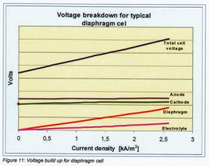
The cell voltage depends on current density. For estimating cell voltages at different current densities it is easy to calculate it via the electrical resistance of the diaphragm cell.
The electrical resistance or K-value can be defined as:
K-value = (Vcell – V0) I|”= (Vcell -2.35) / I”
| K-value = Kw | Electrical resistance | Vm²/kA |
| Vcell | Cell voltage | Volt |
| V0 | Total decomposition voltage | Volt |
| I” | Current density | kA/m2 |
Typical values for Kw are: 0.40< Kw< 0.50 [Vm2/kA]
The K-value can be used for calculating the cell voltage at every Current density
desired.
Vcell = 1″.Kw + 2.35 [Volt]
Current efficiency
The anodic current efficiency can be defined as effective chlorine production in practice divided by the theoretical current needed at a certain current density. Oxygen production at the anode has a significant Influence on decreasing the
anodic current efficiency. Following reactions will illustrate this.
The main anode reaction is:
2 CI– à CI2 + 2 e ——————————(1)
11)
This simple reaction represents approximately 96% of the node discharge under good operating conditions. However the following reactions representing minor losses are oi particular significance since they have a considerable effect on anode life, diaphragm life and purity of the products.
Under normal operating conditions, OH– discharge is the most important anode reaction competitive with chloride discharge:
4 OH– à O2 + 2 H2O + 4e ——————-(2)
The source of OH– ions s the cell liquor, from which the OH– ions migrate under the influence of the electrical potential across he diaphragm.
At equilibrium conditions a certain anolyte pH is established depending on OH– transport through the diaphragm to the anode.
Chlorine formed at the anode saturates the anolyte and an equilibrium is established
CI2 OH– à HOCI (hypochlorous acid)
HOCI à H+ + OCI– (hypochlorite)
These reactions indicate the importance of hydrogen ion concentration on the solubility of chlorine in the anolyte. Normally the pH of the analyte is in the range of 3.5 to 4.5.
Hypochlorous acid and sodium hypochlorite tend to react to produce chlorate according to the bulk reaction:
2 HOCI + OCI– à CIO3– + 2 CI– + 2 H+
Or: 2 HOCI + NaoCI à NaCIO3 + 2 HCI—(3)
Hydrochloric acid + Sodium hypochlorite + Hydrochloric acid
In accordance with reactions (1) and (2), the formation of one gram mol of chlorines requires two faradays (1 F = 96494 Amperes seconds) whereas Formation of mole oxygen requires four faradays.
Assuming that the gases are “perfect” and that all of the gases produced from the cell are derived from anodic processes, the following empiric estimated relationship for current efficiency can be used:
CE= 100 – 2a – ((2.5 + c/135)/(0.03*b))
| CE | = Current efficiency | [%] |
| a | = oxygen in chlorine, on air free base | [vol %] |
| b | = concentration NaOH in cell liquor | [g/I] |
| c | = concentration NaCIO3 in cell liquor | [mg/I] |
Note a =O2 afb = O2 analyzed – 0.27*N2 analyzed
Energy consumption
In general energy consumption depends on:
- Cell voltage
- Load
- Current efficiency
Specific for chlorine it is according to the law of Faraday:
The amount CI2 produced at 1 Faraday 1equilvalent (eq) Cl2= 35.45 gr.
1 Faraday is corresponding with 96500 3600 Ah.
1 ton Cl2 is corresponding with 1000/(35.45) = 28.2 keq. Cl2 (= 28.2*103 Faraday).
Consequently:
1 ton Cl2 net produced corresponds with 28.2*96500/3600 kAh = 756 kAh
Also for the production of 1 ton chlorine net:
Eb= 75600*Voltage/CE
| Eb | = Energy consumption | [kWh/ton Cl2] |
| Voltage | = Cell voltage or average cell voltage of a circuit | [Volt] |
| CE | = Current efficiency of a circuit or cell | [%] |
For comparing energy consumption at different load levels it’s needy to calculate Eb at the same load. The voltage can be calculated with the Kw (Electrical resistance factor).
Productlon
According to the first lew of Faraday it is derived that amounts of products by electrolysis processes are proportional with the load Installed (level and time). The second law Implies that the same load In the same time, transported through different electrolytes, the products are in proportion with their equivalent weights.
For a cell room with diaphragm cells it is derived from the two Laws of Faraday that for the amounts produced by electrolysis the following relation can be applied:
P = ( a * I * n * CE * 3600) / (100 * F) kg/h
| P | Production of CI2, H2 and NaOH | [kg/h] |
| a | = Atomic weights (Cl2=35.5, H2 = 1, NaOH= 40) | [kg] |
| I | = Load | [kA] |
| n | = Number of cells | [–] |
| CE | = Current efficiency | [%] |
| F | = Number of Faraday | [96500] |
Number of faraday is the amount of electrical charge (Amperes seconds or Coulomb), needed for production of 1 gram equivalent (Chlorine, hydrogen and sodium hydroxide).
Example
Load= 60 kA
CE = 96 %
Number of cells = 184
Produced amounts are.
Chlorine:
(35.560184*3600*96)/(100*96500) =
14036 kg Cl2 per hour.
Hydrogen:
(1 60*184″3600 96)/(100*96500) =
395 kg H, per hour.
Sodium hydroxide:
(40 60*184*3600*96)/100*96500) =
15815 ka NaOH per hour.
Benefits Can-Tech cell
Compared with conventional reference cathodes, the newest Can-Tech Advanced Cathode Cans show the following benefits in the field:
- Higher current efficiency by homogeneous current distribution of about 1-2%
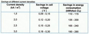
Lower electrical resistance and therefore lower cell voltages of 0,1-0,25 Volt, depending on the current density (1,5 to 2,5 kA/m2)
Next table shows energy savings of Can-Tech Advanced Cathode Cans at different current densities compared with conventional constructions.
Benefits
Feed brine and cell liquor concentration
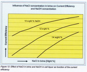
Sodium chloride concentration in the brine effects the sodium chloride concentration in anolyte and also the salt-caustic ratio of the cell liquor produced. It has a significant effect upon current efficiency and on the amount of water which must be evaporated to produce 50% caustic or more.
The relationship between salt-caustic ratio or decomposition ratio and current efficiency is qualitative: ‘the higher NaCl decomposition (or caustic Concentration) ratio, the lower will be the current efficiency.’
The effect of NaCl con centration in the feed brine and thus in anolyte influences the current efficiency at various NaOH concentrations as showing in next figure 12.
The brine flow (Qfeed brine in I/h) per cell for adjusting operating diaphragm cells depends on:
| I” | Current density | [KA/m²] |
| A | Cathode wire screen surface | [m²)
|
| CE | Current efficiency | [%] |
| CNANCI | NaCl concentration in feed brine | [g/I] |
| CNaOH | Sodium hydroxide concentration desired | [g/kg] |
| Qfeed brine | =(4280 8 I”*A*CE) / CNaOH*CNaCI) | [I/h, cell] |
Remark
The relation on the brine flow is available for an anolyte temperature of about 85°C and cell liquor temperature of about 90°C. For other temperatures empirical corrections concerning adjusting feed brine flow are needed for realizing the caustic concentration desired.